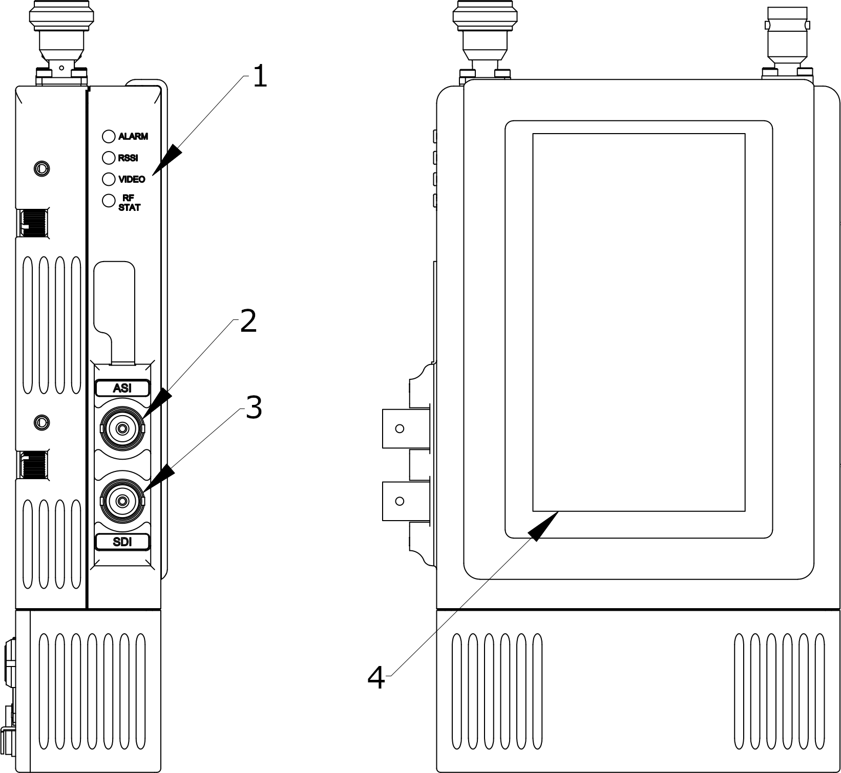
Digital module
The camera back transmitter’s digital module provides a touch screen to configure the transmitter and connectors for video input.

| Key | Component | Description |
|---|---|---|
| 1 | LED indicators | ALARM: Indicates whether there is an error or problem with the camera back transmitter. |
| RSSI: Indicates whether there is a good signal between the data transmitter and the camera back transmitter. | ||
| VIDEO: Indicates whether there is active video input from the camera into the camera back transmitter. | ||
| RF STAT: Indicates the status of the RF module. | ||
| 2 | ASI |
Use to provide an ASI input or output to other Real Freedom or third-party equipment. Connector: BNC (F). |
| 3 | SDI |
Use to connect the camera back transmitter to the camera’s SDI port if you are using SDI as the video source. The transmitter will automatically detect the format as HD-SDI (SMPTE 292) or 3G-SDI (SMPTE 424M). Connector: BNC (F). |
| 4 | Touch-enabled color LCD |
Use to configure the camera back transmitter and view status information. If the screen is dark and there is no display, touch all four quadrants of the screen within one second; trace a U or X pattern on the display to unlock the screen. |
