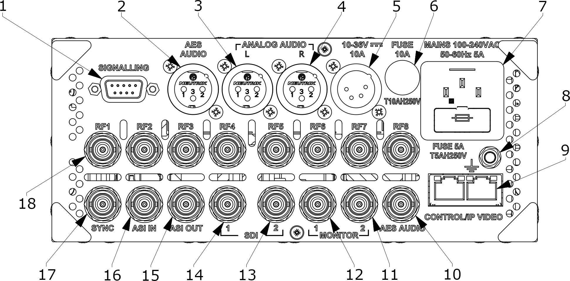
Receiver rear panel
The rear panel of the receiver provides access to the RF inputs, video and audio ports, camera control and power connections.

| Key | Component | Description |
|---|---|---|
| 1 | SIGNALLING |
Provides RS232 control, dry red and green tally closure, and auxiliary controls to client equipment via a DB9 connector. Also allows the connection of BSI accessories, for example, a PTRZ joystick. Connector: 9-pin D-sub (F) |
| 2 | AES AUDIO |
Provides balanced mono audio output, which is less susceptible to noise and interference. Note that balanced AES has a shorter transmission distance (up to 150 m) than the unbalanced version over coaxial cable. Connector: 3-pin XLR (M) |
| 3 | ANALOG AUDIO (L) |
Provides analog stereo audio output to client-supplied equipment. Connector: 3-pin XLR (M) |
| 4 | ANALOG AUDIO (R) | |
| 5 | 10–36V 10 A |
Use to connect the receiver to a DC power source. Connector: 4-pin XLR (M) |
| 6 | FUSE 10A T10AH250V | Fuse for the DC power supply system. |
| 7 |
MAINS 100–240VAC 50–60Hz 5A FUSE 5A T5AH250V |
Use to connect the receiver to an AC power supply. Connector: IEC Fuse for the AC power supply system. |
| 8 | Earth stud | Use to connect the receiver to the equipment rack or some other kind of electrical ground. |
| 9 | CONTROL/IP VIDEO |
Camera control. Use to connect the receiver to a camera control panel either directly or via a network switch. Or use to stream or receive IP video through an Ethernet network connection. Connector: RJ45 |
| 10 | AES AUDIO |
Provides unbalanced audio output using a coaxial cable. Note that unbalanced coaxial cable is better for long distances than balanced twisted-pair cable. Connector: BNC (F) |
| 11 | MONITOR 2 |
Video outputs. Duplicate video outputs with overlaid status information. Connector: BNC (F) |
| 12 | MONITOR 1 | |
| 13 | SDI 2 |
SDI video outputs. Clean video outputs for production use. Connector: BNC (F) |
| 14 | SDI 1 | |
| 15 | ASI OUT |
ASI (compressed video) output. Connector: BNC (F) |
| 16 | ASI IN |
ASI (compressed video) input. Connector: BNC (F) |
| 17 | SYNC |
Provides a connection to a client-supplied B&B or tri-level signal used to synchronize the video image. Connector: BNC (F) |
| 18 | RF1–RF8 |
RF input ports. The Real Freedom Receiver is available with up to eight RF input ports. Each port can be connected to a Real Freedom Downconverter using a standard coaxial cable. Downconverters are available in a variety of frequency bands. Choose the downconverters to match the frequency of the transmitter. Connector: BNC (F) |
