Fiber remote unit
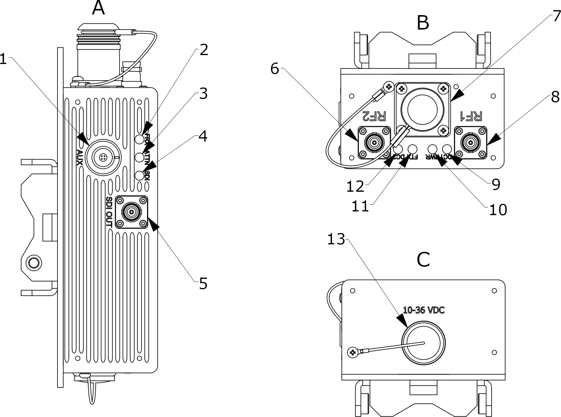
Refer to the following drawing which shows the locations of the connectors on the fiber remote unit. Note for easy identification, the remote unit is grey to match the downconverter.

| Key | Component | Description |
|---|---|---|
| 1 | AUX | Use for programming and firmware updates. |
| 2 | FRX | Indicates the status of optical receive level. |
| 3 | ATTN | Indicates whether remote attenuation is activated. |
| 4 | SDI | Indicates whether a valid SDI signal is being output. |
| 5 | SDI OUT |
SDI/ASI output. Provides an SDI/ASI output if an SDI/ASI source has been connected to the fiber base unit. Note that this interface does not support 3G-SDI. Connector: BNC (F) |
| 6 | RF2 |
Use to connect a Real Freedom Downconverter to the fiber remote unit. Connector: BNC (F) |
| 7 | Fiber connector |
Use to connect the fiber cable to the remote unit. The other end of the fiber cable connects to the fiber base unit. Fiber FC/APC – S & D connectors and SMPTE are typically the most used, but other connector types are available. |
| 8 | RF1 |
Use to connect a Real Freedom Downconverter to the fiber remote unit. Connector: BNC (F) |
| 9 | DC1 | Indicates whether the downconverter on RF1 has power and a comms link with the remote unit. |
| 10 | PWR | Indicates whether the remote unit has DC power and has detected a fiber base unit. |
| 11 | FTX | Indicates the state of the optical fiber transmitters. |
| 12 | DC2 | Indicates whether the downconverter on RF2 has power and a comms link with the remote unit. |
| 13 | 10-36 VDC |
DC input to power the unit. Note that if you are using SMPTE fiber, then the remote unit does not require DC power. Connector: XLR-4 (M) |
