Location and functions of parts
This section provides an overview of the components and connectors on the VyuSync Decoder.
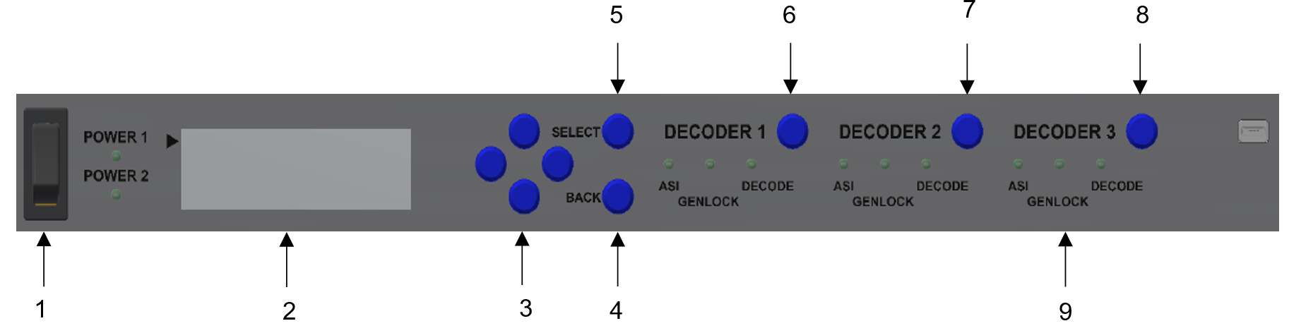
Decoder front panel
| Key | Component | Description |
|---|---|---|
| 1 | Power | Use to power ON or OFF the decoder. |
| 2 | LCD display | Use to view the configurations and status descriptions. |
| 3 | Navigation keys | Use to navigate up/down/left/right through the decoder menu options. |
| 4 | BACK | Use to return to the previous menu option or setting. |
| 5 | SELECT | Use to select or confirm the required setting or option. |
| 6 | DECODER 1 | Use to directly bounce to the Decoder 1 menu options. |
| 7 | DECODER 2 | Use to directly bounce to the Decoder 2 menu options. |
| 8 | DECODER 3 | Use to directly bounce to the Decoder 3 menu options. |
| 9 | LED indicators | Indicates LED status of ASI, GENLOCK, and DECODE for all the three decoders. |
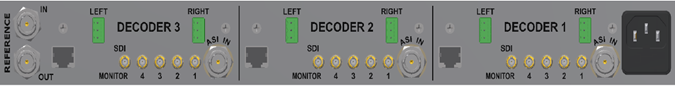
Decoder rear panel
| Key | Component | Description | |
|---|---|---|---|
| 1 | REFERENCE | IN | Defines the state of reference input of the decoder. |
| OUT | Defines the state of reference output of the decoder. | ||
| 2 | LEFT |
Decoded audio output to client-supplied equipment. |
|
| RIGHT | |||
| 3 | SDI | 1 2 3 4 |
SDI video outputs. Clean video outputs for production use. Connector: BNC (F) |
| MONITOR |
Use to monitor the SDI video outputs for debugging purposes. Connector: BNC (F) |
||
| 4 | ASI IN |
ASI (compressed video) input. Connector: BNC (F) |
|