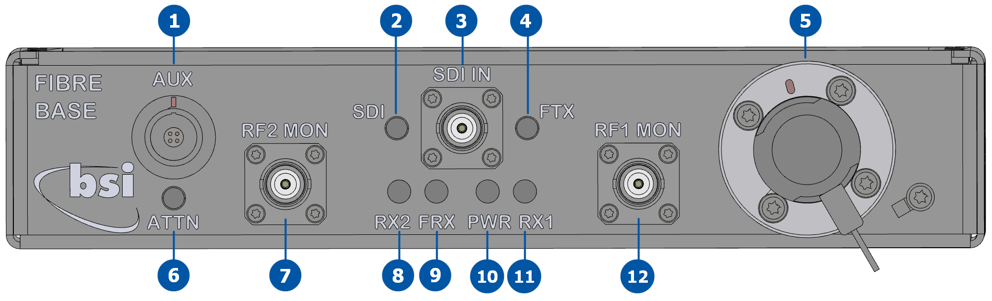
Front panel
The front panel contains the fiber base unit connections.
| Key | Component | Description |
|---|---|---|
| 1 | AUX |
Use for fiber base unit programming and firmware updates. Connector: 4-pin LEMO |
| 2 | SDI | Indicates whether SDI input is activated. |
| 3 | SDI IN |
SDI/ASI input. Use to connect an SDI or ASI source to the fiber base unit to send over the fiber link to the fiber remote unit. Connector: BNC (F) |
| 4 | FTX | Indicates the state of the optical transmitter. |
| 5 | Fiber connector |
Use to connect the fiber cable to the base unit. The other end of the fiber cable connects to the fiber remote unit. Fiber FC/APC – S & D connectors and SMPTE are typically the most used, but other connector types are available. |
| 6 | ATTN | Indicates whether remote attenuation is activated. |
| 7 | RF2 MON |
Use for monitoring purposes only and will usually be connected to a spectrum analyzer. This can, however, be used as an additional output if required. Connector: BNC (F) |
| 8 | RX2 | Indicates whether the fiber base unit RF2 interface is communicating with the receiver. |
| 9 | FRX | Indicates the state of the RF1 and RF2 optical receive levels. |
| 10 | PWR | Indicates whether the base unit is powered and has detected a fiber remote unit. |
| 11 | RX1 | Indicates whether the fiber base unit RF1 interface is communicating with the receiver. |
| 12 | RF1 MON |
Use for monitoring purposes only and will usually be connected to a spectrum analyzer. This can, however, be used as an additional output if required. Connector: BNC (F) |