Connections
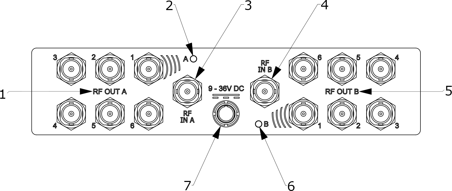
Refer to the following drawing which shows the locations of the connectors on the Real Freedom Active UHF Splitter.

| Key | Component | Description |
|---|---|---|
| 1 | RF OUT A |
Use the RF connectors to split the RF output from RF input A. Each output forms a single RF input to a Real Freedom Receiver allowing you to connect up to six Real Freedom Receivers. You should connect BNC 1 to the Master Real Freedom Receiver that hosts the Connection Map. You can power the splitter on BNC 1 from the Real Freedom Receiver. Connector: BNC (F) |
| 2 | A |
Indicates whether the Real Freedom Active UHF Splitter is powered and in active or passive mode. FLASHING GREEN: Powered and in active mode (additional gain added for splitter loss). FLASHING RED: Powered and in passive mode (no additional gain added for splitter loss). Add a gain boost when RF levels are too low from the receiver’s Fiber & Splitter menu. |
| 3 | RF IN A |
Use to connect the Real Freedom Active UHF Splitter to a Real Freedom Fiber Base Unit (RF1) or to a Real Freedom Downconverter. Connector: BNC (F) |
| 4 | RF IN B |
Use to connect the Real Freedom Active UHF Splitter to a Real Freedom Fiber Base Unit (RF2) or to a Real Freedom Downconverter. Connector: BNC (F) |
| 5 | RF OUT B |
Use the RF connectors to split the RF output from RF input B. Each output forms a single RF input to a Real Freedom Receiver allowing you to connect up to six Real Freedom Receivers. You should connect BNC 1 to the Master Real Freedom Receiver that hosts the Connection Map. You can power the splitter on BNC 1 from the Real Freedom Receiver. Connector: BNC (F) |
| 6 | B |
Indicates whether the Real Freedom Active UHF Splitter is powered and in active or passive mode. FLASHING GREEN: Powered and in active mode (additional gain added for splitter loss). FLASHING RED: Powered and in passive mode (no additional gain added for splitter loss). Add a gain boost when RF levels are too low from the receiver’s Fiber & Splitter menu. |
| 7 | 9–36 V DC |
Use to power the Real Freedom Active UHF Splitter. DC power is required if you do not want to use the receiver’s phantom power or when using the splitter with third-party equipment. Note that the splitter has a fail-safe passive mode of operation when no power is available, or power is lost. Connector: 4-pin LEMO |
