Camera control settings
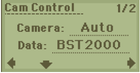
Tap the camera number icon to display the Camera Control page. Use this page to enter details of the of the camera that you are using. It is important to enter all the settings correctly so that the camera transmitter can communicate with the camera.
When you have selected the appropriate settings, toggle the joystick left to return to the main page.
 |
 |
| Setting | Description | ||||||||||||||
|---|---|---|---|---|---|---|---|---|---|---|---|---|---|---|---|
| Cam Control |
You need to set the required camera control frequency, which is the frequency used by the data transmitter to send camera control data to the Mini-Tx UHD. You also need to ensure that the camera type and it’s ID are set correctly. Tap the current value, change the numbers to the required frequency by toggling the joystick up/down. |
||||||||||||||
| Camera Type/Protocol |
Defines the camera type – Auto, Sony, POV, Ike, GV, Pelco, Visca, In car, Dchip Tap the current type, toggle the joystick up/down to choose the camera type that you want. |
||||||||||||||
| Call: Sony |
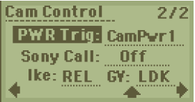
Camera Type set to ‘Sony’. Sony Call is required on Sony camcorder-style cameras to allow tally to operate. |
||||||||||||||
| GV Series |
Camera Type set to ‘Grass Valley’. Tap to define the camera series, either ‘LDK’ or ‘LDX’. |
||||||||||||||
| Ikegami Mode |
Camera Type set to ‘Ikegami’. Tap to select the value mode, ‘Absolute’ or ‘Relative’. Refer to the camera’s operator control panel manual for an explanation of these settings. |
||||||||||||||
| Power Trigger | In the web/UI menu configuration, you now have the below options for
external Tally.
Notice: This configuration for
camera control power pin is available on Mini-Tx UHD single input
front panel board from software update v3.2.5 only. Important: This output is a battery
voltage pass-thru and this will probably require some external
regulation to drive a tally LED. The output has a load switch to
protect against short-circuit and the usual on-site miss wiring
etc. |
Table 5: Camera control settings
